| Integrated Flue Gas Treatment Technology (IFGT) |
| The fluid catalytic cracking (FCC) process is one of the most important oil refining process, in which heavy oil is converted to light fraction. The FCC catalyst regeneration generates flue gas containing SO2, NOx and particulates, and pollution treatment before discharge is required to meet the emission regulations. The integrated FCC flue gas treatment technology offered by JNG seamlessly integrates state-of-the-art SO2, NOx and PM control technologies, and provides an efficient and cost-effective solution to FCC flue gas treatment requirements. |
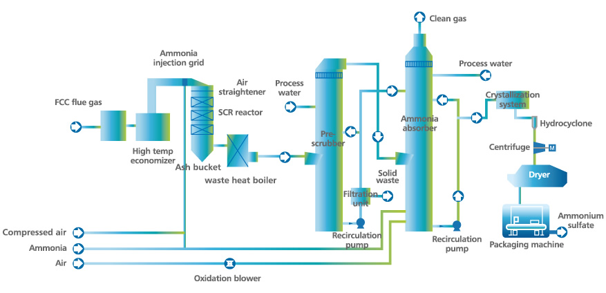
| Process Flow A: SCR + Wet Dust Scrubbing + EADS |
| Flue gas from the FCC catalyst regeneration process recovers thermal energy through an expander and waste heat recovery boiler before entering the SCR (Selective Catalytic Reduction) reactor at a specified (300℃~420℃) temperature. In the presence of the SCR catalyst, NOx in the flue gas reacts with ammonia and produces N2 and H2O. After NOx removal, the flue gas goes through the low temperature waste heat recovery boiler, and then is fed into the pre-scrubber to remove particulates. The solution with dust from the pre-scrubber is sent back to the scrubber system after filtration. The flue gas is sentto the ammonia absorber to remove SO2. After the cooling, scrubbing, absorption and demisting steps, the clean flue gas is discharged from stack above the absorber. |
| The product of the initial reaction between SO2 and the ammonia-based absorbent is ammonium sulfite. Through oxidation and concentration, ammonium sulfite in the aqueous solutions converted into ammonium sulfate with a precisely controlled concentration. The ammonium sulfate slurry is further processed in the hydrocyclone, the centrifuge, and the dryer to yield ammonium sulfate with water content less than 1%. The ammonium sulfate is then packaged in the packaging machine and palletized as fertilizer-grade ammonium sulfate product. Besides, There is no waste water generated in the whole technological process. |
| The complete process system consists of SCR denitration unit, desulfurization and PM control unit. The FGD and PM control unit includes flue gas system, dust removal system, absorption-circulation system, oxidation air system, absorbent system, filtration system, process water system, evaporation crystallization system, ammonium sulfate system, maintenance and blow down system. |
· NOx emissions ≤ 100 mg/Nm3
· SO2 emissions ≤ 50 mg/Nm3, can reach to 35 mg/Nm3
· PM emissions ≤ 10 mg/Nm3 |
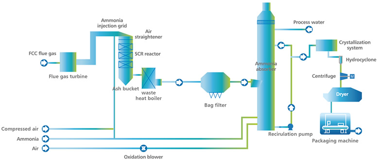
| Process Flow B: SCR + Bag filter + EADS |
| Flue gas from the FCC catalyst regeneration process recovers thermal energy through an expander and waste heat recovery boiler before entering the SCR (Selective Catalytic Reduction) reactor at a specified (300℃~420℃) temperature. In the presence of the SCR catalyst, NOx in the flue gas reacts with ammonia and produces N2 and H2O. After NOx removal, the flue gas goes through low temperature waste heat recovery boiler, and then is fed into the bag filter to remove particulates and then to the ammonia absorber to remove SO2. After the cooling, scrubbing, absorption and demisting steps, the clean flue gas is discharged from stack above the absorber. The product of the initial reaction between SO2 and the ammonia-based absorbent is ammonium sulfite. Through oxidation and concentration, ammonium sulfite in the aqueous solutions converted into ammonium sulfate with a precisely controlled concentration. The ammonium sulfate slurry is further processed in the hydrocyclone, the centrifuge, and the dryer to yield ammonium sulfate with water content less than 1%. The ammonium sulfate is then packaged in the packaging machine and palletized as fertilizer-grade ammonium sulfate product. Besides, There is no waste water generated in the whole procedure. |
| The complete process system consists of SCR denitration unit, desulfurization and PM control unit. The FGD and PM control unit includes flue gas system, bag filtersystem, absorption-circulation system, oxidation air system, absorbent system, filtration system, process water system, evaporation crystallization system, ammonium sulfate system, maintenance and blow down system. |
· NOx emissions ≤ 100 mg/Nm3
· SO2 emissions ≤ 50 mg/Nm3, can reach to 35 mg/Nm3
· PM emissions ≤ 10 mg/Nm3 |
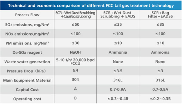
| The typical FCC flue gas treatment process is SCR for NOx removal and caustic scrubbing process for SO2 and PM removal. Compared to the conventional process, JNG’s IFGT technology saves 10%~30% of the capital cost and more than 50% of the operating cost while achieving the same air pollution control efficiency (SO2 emission ≤ 50 mg/Nm3, can reach to 35 mg/Nm3, NOx emission ≤ 100 mg/Nm3, PM emission ≤ 10 mg/Nm3). Besides, the system generates no salty waste water, no secondary treatment costs, and the byproduct ammonium sulfate. |
| The typical FCC flue gas treatment process is SCR for NOx removal and a caustic scrubbing process for SO2 and PM removal. Compared to the conventional process, JNG (China)'s IFGT technology saves 20% to 40% of the capital cost and more than 10% of the operating cost while achieving the same air pollutant control efficiency (NOx emissions ≤ 100 mg/Nm3, SO2 emissions ≤ 50 mg/Nm3, PM emissions ≤ 30 mg/Nm3). Besides, the system generates no waste water. |
|